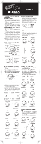
96M11513 FS-N10 Series Quick Start „ Quick Start Digital Fiber Sensor Mode/Output *2 Fine sensitivity adjustment FS-N10 Series Up Press the [MODE] button once, then use to select L-on or D-on Down Preset function Instruction Manual Configure easily with a single press when receiving light Setting value Light intensity Power select switch *1 Sensitivity setting Standard ⇔ MEGA (fixed) Press once each for workpiece/no workpiece *1 This is a channel switch on 2-output types. This is not equipped with the 0-line type. *2 Press and hold the [MODE] button to make advanced setting changes. Names of Each Part of the Main Unit and Expansion Unit Fiber lock lever SET button (SET) Read this manual before using the product in order to achieve maximum performance. Keep this manual in a safe place after reading it so that it can be used at any time. Danger Failure to follow these instructions may lead to death or serious injury. Warning Failure to follow these instructions may lead to injury. Caution Failure to follow these instructions may lead to product damage (product malfunction, etc.) Operation status indicators PST indicator Sub screen (Displayed in green) DTM indicator Digital display Note Manual button ( ) Main screen (Displayed in red) Expansion protective cover Expansion connector Provides additional information on proper operation. MODE button (MODE) Preset button (PRESET) This provides useful tips for the feature being described. Cable*2 Tip Power select switch*1 Dust cover See "FS-N10 Series User's Manual" for details on the features of the FS-N10 Series and detailed instructions for configuration. *1 Setting to "M" locks the power mode to MEGA mode. The switch is a channel switch for the two output type. This is not equipped with the 0-line type. *2 On the FS-N1…C…, this is an M8 connector rather than a cable. On the FS-N1…EN, this is an e-CON connector. Hints on Correct Use Mounting Unit • This product is just intended to detect the object(s). Do not Warning „ Mounting on a DIN Rail use this product for the purpose to protect a human body or a part of human body. • This product is not intended for use as explosion-proof product. Do not use this product in a hazardous location and/or potentially explosive atmosphere. • This product uses DC power. Do not apply AC power. The product may explode or burn if an AC voltage is applied. 1 2 • Do not wire the amplifier line along with power lines or high-tension lines, as the sensor may malfunction or be damaged due to noise. • When using a commercially available switching regulator, ground the frame ground terminal 3 Align the claw at the bottom of the main body with the DIN rail, as shown in figure1. While pushing the main body in the direction of the arrow 1, push down in the direction of arrow 2. 2 1 figure1 To dismount the sensor, raise the main body in the direction of the arrow 3 while pushing the main body in the direction of arrow 1. „ Installation on a Wall (Main Unit Only) and ground terminal. • Do not use the FS Series outdoors, or in a place where extraneous light can enter the light- 1 receiving element directly. • Due to individual dispersion characteristics and the difference in fiber unit models, the maximum sensing distance or displayed value may not be the same on all units. Attach the unit to the optional mounting bracket (OP73880), and secure with two M3 screws as shown in figure2. • If the sensor is used for a long time with the APC function enabled and the LED is imposed with a heavy load, the current consumption of the sensor for light emission will become constant and 'END APC' will be displayed. The sensor can still be used in this case. However, replace the sensor if even small changes in received light intensity should be detected for precise detection. OP-73880 figure2 Connecting Fiber Unit Precautions on Regulations and Standards 1 „ UL Certificate 2 This product is an UL/C-UL Listed product. • UL File No. E301717 • Category NRKH,NRKH7 • Enclosure Type 1 (Based on UL50) 3 4 Be sure to consider the following specifications when using this product as an UL/C-UL Listed Product. • Use the power supply with Class 2 output defined in NFPA70 (NEC: National Electrical Code). • Power supply/ Control input/ Control output shall be connected to a single Class 2 source only. • Use with the over current protection device which is rated 30V or more and not more than 1A. Included accessories • Instruction Manual 1pc. 1 Open the dust cover in the direction shown by arrow 1. 1 Move the fiber lock lever in the direction shown by arrow 2. Insert a fiber unit into the amplifier as indicated by arrow 3 (approximately 14 mm). Move the fiber lock lever in the direction shown by arrow 4 to secure the fiber. 4 2 3 Fiber insertion sign . Note Other Calibration Methods • If a thin fiber unit is used, an adapter provided with the thin fiber unit will be required. Unless the correct adapter is connected, the thin fiber unit will be loose and not detect targets correctly (the adapter is supplied with the fiber unit). Cable outer dia Adapter φ1.3 Adapter A (OP-26500) φ1.0 Adapter B (OP-26501) „ Increased Resistance to Dust and Dirt z Appearance Maximum Sensitivity Calibration In the state shown below, press and hold the [SET] button for three seconds or more. Stop pushing when "5'6" flashes. The sensitivity is set slightly higher than the received light intensity. Thrubeam model : with workpiece Workpiece • To connect the coaxial reflective type fiber unit to the amplifier, connect the single-core fiber to the transmitter side, and connect the multiple-core fiber to the receiver side. Single-core fiber Multi-core fiber Press and hold for 3 seconds or more Transmitter Reflective model : without workpiece Receiver Press and hold for 3 seconds or more Connecting Multiple Amplifiers Up to 16 expansion units can be connected to one main unit. However, two output types will be treated as two main units. Warning Note 1 2 „ Calibrate with a Moving Workpiece Mount on DIN rail and install on metal surface when connecting to multiple amplifiers or mounting main units together. z Fully Automatic Calibration Press and hold the [SET] button with no workpiece in place. While “5'6” is flashing, pass a workpiece through. (Continue pressing the [SET] button while the workpiece passes through.) • When connecting with units other than N-bus (a general term for the KEYENCE wire-saving connection system) compatible sensor amplifiers, including the FS-N10 Series, and the network unit NU Series, consult your nearest KEYENCE dealer. • Turn the power off before connecting multiple expansion units. • Do not touch the expansion connector with your bare hands. Common to Thrubeam and Reflective Models Press and hold until "UGV" flashes Remove the protection covers from the main unit and expansion unit(s). Install the amplifiers on the DIN rail one at a time. While pressing the [SET] button pass through a workpiece 3 4 5 Workpiece Slide the main unit and expansion unit(s) together. Engage the two claws of the expansion unit with the recesses on the main unit side until you hear/ feel a click. Settings complete „ Position Workpiece z Attach the end units (option: OP-26751) to the DIN rail in the same way as step (2). Positioning Calibration Press the [SET] button with no workpiece. Place the workpiece in the location you wish to position it. Press and hold the [SET] button for at least 3 seconds. Release the button when "5'6" flashes. Secure the amplifiers between the end units. Tighten the screws at the top (two screws x two units) with a Phillips screwdriver to fix the end units. Common to Thrubeam and Reflective Models Press [SET] button once with no workpiece OP-26751 (a set of two) Calibration Method „ Detecting Even Small Differences z Press and hold [SET] button with workpiece Two-point Calibration Two-point calibration is the basic method of calibration. Press the [SET] button once without the workpiece, and then press it once again with the workpiece. 1 Press and hold until "UGV" flashes Press the [SET] button with no workpiece. [SET] will be displayed on the sub-menu (green display). Workpiece Settings complete Simple, User Friendly Functions 2 „ Setting the Current Value to 100.0 Press the [SET] button with workpiece. The values will be set and the submenu (green display) will flash. The values will be set to the mid-point between the light intensity when there is no workpiece, and the light intensity when there is a workpiece. With the FS-N10 Series, you can set the current value to 100.0 using simple operations. Standardizing the current value makes it possible for the sensor amplifiers to instantly differentiate reductions in light intensity and is useful in predicting the need for maintenance. Note Workpiece Workpiece If "----" flashes for two seconds on the main screen, the light intensity is too small between conditions when the workpiece is absent and when it is present. These values will be set, but there is the possibility that detection may become unstable. Tip 2 • The various Preset functions listed below cannot be used when the ZeroShift function is enabled. Disable the Zero-Shift function before executing the following functions. • The Preset functions are not suited for transparent workpieces and other cases of detection with low light intensity differences. You can disable various Preset functions by pressing and holding the [PRESET] button. z z Preset Function This function adjusts the current value to "". With light received, press the [PRESET] button. The current value is set to "". Full Auto Preset Function This function automatically differentiates between two conditions (presence/absence of workpiece) and adjusts the current values to "" and "". This is effective for cases when the workpiece is moving at high-speed. Press and hold the [PRESET] button with no workpiece in place. While "#WVQ" is flashing, pass a workpiece through. (Continue pressing the [PRESET] button while the workpiece passes through.) Press [PRESET] button once with no workpiece Common ・ to Thrubeam and Reflective Models Green "PST" lights up Setting is "" Current value is "" Press and hold until "#WVQ" flashes Pressing the [PRESET] button changes the setting and current value as shown below. • Presetting with preset disabled: The setting is changed to "". The setting can be changed via the normal calibration method. • Presetting with preset enabled: Only the current value is changed to "", and the setting is not changed. While pressing the [PRESET] button pass through a workpiece . Handy Uses for the Preset Function Tip z This function is most useful when performing simple detection using a thrubeam model fiber unit (e.g. completely blocked detection, such as when all light axes of the fiber unit are interrupted by opaque workpieces). Workpiece Settings complete Work-Preset Function • Near-maximum values while the [PRESET] button is being pressed and held are This function adjusts the current value to "". After executing the Preset function in a condition in which you would like "" to be displayed, executing this function in a condition in which you would like "" to be displayed, will adjust any two points to "" and "". • The setting value is changed to "" • The green [PST] indicator will light up. Important adjusted to "" and near-minimum values are adjusted to "" . Note The Work-Preset function can be used while the Preset function is in use (when Preset is enabled). Cannot be executed when the Preset function is already being used (when the [PST] indicator is flashing). Press and hold the [PRESET] button to disable the Preset function before executing this function. „ Set Current Value to "0" Pressing the [PRESET] button and the button at the same time will set the current value at that time to "". Values that have been set to "" with the Preset function cannot be changed. z The Zero Shift Function This function is primarily used with reflective models. Press the [PRESET] button and button at the same time. 100.0 Workpiece 3.0 .0 [PRESET] + Green "PST" lights up • The current value is set to "". • Green "PST" lights up Note z z Disable the Zero Shift Function Press and hold the [PRESET] button to disable the zero shift function. Current value is "" Tip The zero shift and preset function cannot be used together. To use the preset function, you must first disable the zero shift function. Handy Uses for the Zero Shift Function When using this function with reflective models, "" will be displayed when there is a workpiece, and "" will be displayed when there is no workpiece, making it easy to know when the workpiece is present or absent. Additionally, even when with a reflective model, the background has higher light intensity than the workpiece, if you set a condition with low light intensity to "" using the Preset function and then using the Work-Preset function, register a condition with high light intensity as "", the background will display as "" and when the workpiece is present, it will be displayed as "". Tip This function is primarily used to set the current value to "0" on a reflective model fiber unit. When a reflective model is first installed, the light intensity is sometimes not set to "0". If this happens, using the zero shift function to set the value to "0" when there is no workpiece allows for easier understanding of the difference in light intensity. „ Adjusting the current intensity value when it is too large (when saturated). Maximum Sensitivity Preset Function This function sets conditions that will serve as reference, to "" and adjusts conditions with slightly high light intensity as "". This is useful when you would like to perform detection using the background as a reference with reflective models. In the following conditions, press and hold the [PRESET] button for 3 seconds or more then release your finger when "#WVQ" is flashed. z Use the Saturation Recovery Function Press the [SET] button while pressing the [MODE] button. Thrubeam model : with workpiece Workpiece Press the [SET] button while pressing the [MODE] button. Press and hold for 3 seconds or more After adjusting the light transmission level and light intensity sensitivity, the current values will be adjusted to within the ranges listed in the table that follows. Reflective model : without workpiece Power mode HSP*, FINE, TURBO SUPER ULTRA, MEGA Light intensity setting range 2047 ± 350 4095 ± 500 5000 ± 600 Press and hold for 3 seconds or more *HIGH SPEED • The maximum value for the light intensity while the [PRESET] button is being pressed is • • Note z set to ", and light-intensity that is slightly higher than the maximum value at that time will be adjusted to "". The setting value is "" The green [PST] indicator will light up. Disable Saturation Recovery When the saturation recovery function is enabled, press the [SET] button while pressing the [MODE] button to cancel it. Handy Uses for the Saturation Recovery Function Cannot be executed when the Preset function is already being used (when the [PST] indicator is flashing). Press and hold the [PRESET] button to disable the Preset function before executing this function. Tip 3 This function is useful when the intensity value is saturated after installation. This function corrects the saturation via a simple operation, by automatically calibrating the light transmission level and light intensity gain. Output Switch Initializing the Settings „ Initialization Method Either light-ON (L-on) mode or dark-ON (D-on) mode can be selected. 1 2 While the current value is displayed, press the [MODE] button once. 1 Use to switch the output (.QP/&QP), then press the [MODE] button again. The output change completes, and the display returns to the current value. Press and hold for 3 seconds or more 2 3 Connecting to External Devices „ Cable Types FS-N11N/N12N/N13N/N14N z FS-N11P/N12P/N13P/N14P Brown*1 Initial Settings Initial Value Pink*2 current 1 mA or less) Blue FINE Detection mode Std (Normal) Setting value 50 Output switch L-on 0V *1 *1 FS-N11P/N13P only *2 FS-N13P/N14P only Using a Fiber Cutter and Cautions for Use „ Using a Fiber Cutter FS-N11MN Brown Protection circuit Use the to select "K0K6", then press the [MODE] button. After initialization is complete, the display returns to the current value. Power mode Load Load White (Control output 2)*2 0V *1 *1 FS-N11N/N13N only *2 FS-N13N/N14N only Overcurrent protection circuit to select "456", then press the [MODE] button. Setting (Short-circuit current 2 mA or less) Black (Control output 1) PLC, etc. (Short-circuit Pink*2 Blue *2 Overcurrent protection circuit Sensor main circuit White (Control output 2) Use the PLC, etc. Black (Control output 1) DC3.3V 12 to 24 VDC Brown*1 Load Load Overcurrent protection circuit Sensor main circuit 12 to 24 VDC Sensor main circuit Press and hold the [SET] and [PRESET] buttons simultaneously for three seconds. 1 2 12 to 24 VDC Orange Monitor output (1 to 5V) Black Load (Control output) Blue Device with input impedance 10 kΩ or more Insert the fiber into the cutter hole. Bring down the blade in a single, swift motion to cut the fiber. 2 0V Fiber „ M8/e-CON Connector Types FS-N11CN/N12CN/N11EN/N12EN 1 Always insert fiber from the side with writing FS-N11CP/N12CP/N13CP/N14CP 12 to 24 VDC 12 to 24 VDC PLC, etc. (Short-circuit (Control output 2)*2 current 1 mA or less) Failure to follow the cautions below could reduce the detection range. *3 0V *1 2 1 4 3 • When cutting a fiber unit to be attached to the FS-N10 Series, be sure to use a gray fiber cut- 0V *1 *1 FS-N11CN/N11EN only • The fiber cutter comes with the fiber unit. Load DC3.3V (Short-circuit current 2 mA or less) (Control output 1) Load Sensor main circuit Overcurrent protection circuit PLC, etc. (Control output) M8 connector Pin layout „ Cautions for Using a Fiber Cutter *1 Load Overcurrent protection circuit Sensor main circuit *1 Fiber cutter (OP-87098) ter (OP-87098) • Stopping the blade midway could cause a bad cut plane, reducing the detection range. • Do not use the same hole twice. *1 FS-N11CP/N13CP only *2 FS-N13CP/N14CP only *3 FS-N11CP/N12CP only FS-N11CN/N12CN 2 M8 connector Pin layout 1 4 Function Configuration 3 e-CON connector Pin layout „ Basic Setting FS-N11EN/N12EN MODE Press and hold „ M8 connector Cable (Sold Separately) for 3 seconds or more J52 (KPG 6WT$ 5W24 7.64 /')# For FS-N11CN/N11CP/N12CN/N12CP/N13CP/N14CP HIGH SPEED mode MODE OP-73864 (Cable length: 2 m) 4 3 OP-73865 (Cable length: 10 m) 2 1 Pin - Pin and wire color table Connected Wire color pin No. 1 Brown 2 White 3 Blue 4 Black FINE mode TURBO mode SUPER mode ULTRA mode MEGA mode 5'6 5VF 5'6 5'V2 5'6 15'V Error Displays and Corrective Actions Normal sensitivity setting method MODE Error display Cause Solution Check the load and return the current within the rated value. ErC Overcurrent in the control output. ErE Failed to write/load the internal data. Perform initialization (p.4). End APC Loc Large load on the light source. Replace the sensor if highly precise detection is required. The keylock function is ON. For disabling (setting) method, see "FS-N10 Series User's Manual". MODE Consult your nearest KEYENCE office regarding error displays other than the ones listed above. '0& 5V) (W0E 5V) &K52 5V) 5;5 Percentage Calibration*1 Zero-shift calibration MODE Settings complete Go to detection setup mode Go to display setup mode Go to system setup mode Return to normal display *1 You can press the 4 MODE button to set between the range of 2 to 2. „ Detection Settings „ System Settings Disable APC Timer OFF Off-delay timer *1 Enable APC 1 On-delay timer * Eco feature off One-shot timer *1 Enable eco feature Normal (light intensity) detection mode Reduce power consumption (response time 4 times slower) DATUM1 mode *2 Standard current value display DATUM2 mode *2 Area detection mode Maximum current value display (4 times hysteresis) Rising Edge Detection Mode Normal operation Falling Edge Detection Mode Twice the number of interference-prevention units as 56& (response time 2 times slower) External input off *6 *1 Disable common key operations External calibration input Enable common key operations Preset input Zero shift input Settings complete Reset input Go to detection setup mode Go to original display setup mode Light transmission OFF input 3 Return to system setup mode Pause mode transition input * Sleep mode transition input Return to normal display Light emission power selection * *1 Main unit only. Analog scaling *5 „ Two Output *2 4 *7 Light intensity detection mode Settings complete Limit setting output mode Go to display setup mode Go to system setup mode User reset Return to original detection setup mode Auto reset Return to normal display *1 Press the MODE Warning output mode button to set between the range of and (ms). MODE Timer OFF *2 Press the button to set the retouch sensitivity to a range of between .'W and .'W and set the warning output level to a range of between 12 and 2. Off-delay timer *1 MODE Press the button to toggle between Q((/Q0/-''2. Can be set between the range of and . Can be set between the range of and . Can be used only for the types with the external input. Note that these functions can be used via communication when connecting with the network unit NU Series. *7 Only monitor output types (FS-N11MN). *3 *4 *5 *6 On-delay timer *1 One-shot timer *1 Settings complete „ Display Settings Return to normal display *1 Press the Reverse display Sub-display off Extended display Bar display Excess gain display Light intensity hold display *1 Excess gain hold display *1 L-on / D-on display Enable the saturation of the Preset function *2 Disable the saturation of the Preset function Settings complete Go to system setup mode Go to detection setup mode Return to original display setup mode Return to normal display *2 Press the MODE MODE button to set between the range of and (ms). *2 Only 2 output types (FS-N13N/N13P/N14N/N14P/N13CP/N14CP). Normal display method *1 Press the MODE button to toggle between 5VF/2`2A/D`DA/2AD`/2`DA button to set between the range of 2 and 2. 5 Specifications Type Cable/M8 connector Main unit/expansion unit Standard 1 output Cable Expansion unit Main unit (with output cable) Model NPN PNP Control output Monitor output (1 to 5 V) External input Light source LED Response time FS-N11N FS-N11P 1 output - FS-N12N FS-N12P 1 output - M8 connector*1 Expansion unit Main unit (with output cable) FS-N11CN FS-N11CP 1 output 1 input FS-N12CN FS-N12CP 1 output 1 input e-CON connector*1 Expansion unit Main unit (with output cable) (with output cable) FS-N13CP 2 output - FS-N14CP 2 output - (without output cable) FS-N11MN 1 output 1 output - FS-N10 N/A*2 - 1 to 5 V voltage output; load resistance 10 kΩ or more; repeat precision ± 0.5% of F.S.; 1 ms response time (HIGH SPEED, FINE, TURBO)*4 Monitor output*3 External input input time 2 ms (ON)/20 ms (OFF) or more*5 Up to 16 units can be connected (total of 17 units including the main unit). Note that the two-output type is counted as two units. Protection against reverse power connection, output overcurrent, and output surge Expansion Units Protection circuit Number of interference prevention units Rating Power voltage 0 for HIGH SPEED; 4 for FINE; 8 for TURBO/SUPER/ULTRA/MEGA (When set to double, the number of interference-prevention units will be doubled.) 12 to 24 V DC ± 10% ripple (P-P) 10% or less NPN Normal:900 mW or less (36 mA max. at 24 V, 48 mA max. at 12 V)*6 Eco on mode:800 mW or less (32 mA max. at 24 V, 39 mA max. at 12 V)*6 Eco Full mode:470 mW or less (19 mA max. at 24 V, 23 mA max. at 12 V) PNP Normal : 950 mW or less (39 mA max. at 24 V, 52 mA max. at 12 V)*6 Eco on mode : 850 mW or less (35 mA max. at 24 V, 44 mA max. at 12 V)*6 Eco Full mode : 520 mW or less (21 mA max. at 24 V, 26 mA max. at 12 V) Environme Operating ambient ntal luminance resistance Operating ambient temperature Operating ambient humidity Vibration resistance Shock resistance *1 *2 *3 *4 *5 *6 *7 (with output cable) FS-N11EN FS-N12EN FS-N13N FS-N14N FS-N13P FS-N14P 1 output 1 output 2 output 2 output 1 input 1 input 1 input 1 input Red 4-element LED (wavelength 630 nm) 50 μs (HIGH SPEED)/250 μs (FINE)/500 μs (TURBO)/1 ms (SUPER)/4 ms (ULTRA)/16 ms (MEGA) Light-ON/dark-ON toggle Timer OFF, OFF delay, ON delay, One-shot NPN open collector 24 V; 1 output max: 100 mA or less; 2 output total: 100 mA or less (used stand-alone)/20 mA or less (multiple connections); residual voltage 1 V or less PNP open collector 24 V; 1 output max: 100 mA or less; 2 output total: 100 mA or less (used stand-alone)/20 mA or less (multiple connections); residual voltage 1 V or less Output toggle Timer function Control NPN output output PNP output Case material Case dimensions Weight High functionality 2 output Monitor output 0-line Cable Cable M8 connector*1 Expansion unit Expansion unit Main unit Expansion unit Main unit Main unit Normal : 1050 mW or less (42 mA max. at 24 V, 56 mA max. at 12 V)*6 Eco on mode : 950 mW or less (38 mA max. at 24 V, 47 mA max. at 12 V)*6 - Eco Full mode : 600 mW or less (24 mA max. at 24 V, 29 mA max. at 12 V) Incandescent lamp: 20,000 lx or less; Sunlight: 30,000 lx or less -20 to +55 ° C (no freezing)*7 35 to 85% RH (no condensation) 10 to 55 Hz Compound amplitude 1.5 mm, 2 hours for each of X,Y,Z axis Approx 75g Approx 45g Approx 22g 500 m/s2 3 times for each of X,Y,Z axis Both main unit and expansion unit housing material: Polycarbonate H30.3mm x W9.8mm x L71.8mm Approx 22g Approx 22g Approx 22g Approx 80g Approx 70g Approx 22g Approx 22g Approx 75g Approx 20g Use a cable length of 30 m or less for M8 connector and e-CON connector types. Counted as 1 output when connecting with the network unit NU Series. FS-N11MN only SUPER : 1.2 ms, ULTRA : 1.8ms, MEGA : 4.2 ms Input time is 25 ms (ON)/25 ms (OFF) only when external calibration input is selected. Increases 100 mW (4.0 mA) for High Speed mode One or two more units connected: -20 to +55 ° C; 3 to 10 more units connected: -20 to +50° C; 11 to 16 more units connected: -20 to +45° C. When using 2-outputs, one unit is counted as two units. All temperature regulations are for when the unit is mounted on a DIN rail and installed on metal sheeting. strument Instru mentaation for Science and Industry ISI sa-nv Rue du Doyenné 3 - 1180 Brussels Tel +32 (0) 2 343 30 81 Fax 02/ 343 12 05 web : http:// www.isi-be.com mail : [email protected]
© Copyright 2026 Paperzz